
Ultracompact ultralow power ECR technology

An ECR plasma cavity as small as a thumb
The core element of our products is a patented microwave discharge system as small as a thumb. The founders of Polygon Physics developed the first one in 2009 at a French research lab as a low cost microwave ion source for surface treatment purposes. Generally, when designing such a source, a magnetron is chosen as microwave power supply. This works nicely, but the coupling of the magnetron to the discharge chamber induces quite a lot of mechanical and microwave constraints (e.g. impedance matching). For COMIC and TES, they decided to use a transmitter comparable to the ones used inside cellular phones (peak power around 2 GHz, in the range of 1 W) with a matching resonant microwave cavity. At such low power the geometry needs to be very compact. The end result easily fits into the palm of your hand.
ECR plasma in short
ECR plasma in more detail
An ECR plasma source uses a magnetic field and a microwave to heat up electrons up to the point that they can ionize the gas molecules. In our technology the magnetic field is generated by permanent magnets around a central plasma cavity. Free electrons circle around the magnetic field lines inside the cavity due to the Lorentz force, with frequency
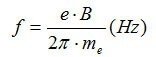
where B is the magnetic flux density, e the electron charge, and m the electron charge. A nonzero velocity component parallel to the magnetic field will cause an electron to spiral along the field lines with a helical path. A nonzero velocity component in a different direction will result in a cycloidal type of path with a net drift perpendicular to the magnetic field.
When sending in the microwave we add an alternating electromagnetic field perpendicular to the magnetic field. In the special case that the microwave frequency exactly matches the angular frequency of the electrons, the free electrons are continuously accelerated (‘heat up’) because they change direction in phase with the alternating electric field. For the microwave of 2.45 GHz that we use, this resonance condition is met for a magnetic field strength of 875 Gauss. When this condition is met, the input power is efficiently transferred to the electrons (maximum energy absorption of the supplied electric field).
The free electrons can ionize gas molecules when they transfer sufficient energy in a collision to liberate an electron (the ionization energy for argon is for example about 16 eV). This means that the mean free path of the electrons needs to be long enough to have enough time to accelerate. In other words, the gas pressure cannot be too high.
Extracting beams from the ECR plasma cavity
The ECR plasma cavity serves as the source of the ions or electrons that we make beams of. We extract the beams from the cavity with the help of electromagnetic fields. First of all, with permanent magnets around the cavity we induce a magnetic field gradient at the cavity exit. We also create an electric field at the cavity exit by applying a bias to the cavity. For ion beams the cavity is biased positively with respect to ground. For electron beams the cavity is brought to a negative potential. With the plasma cavity biased, also the microwave power to ignite and sustain the plasma has to be brought from ground to that potential. This is not always straightforward, but for the 2.45 GHz power we typically use, we have developed a very effective vacuum-compatible coaxial high voltage insulator.


Optics: focused, parallel, or divergent beams
Cavity arrays: ion beam(s) of any dimension
Key parameters for ion beams used for surface treatment processes are beam energy, and (variation of) current density of the beam across a given surface area.
The maximum beam current that can be extracted from a single cavity source is ultimately limited by the applied microwave power and the gas ionization efficiency. Some applications require higher beam currents, or require a current density distribution different than a single cavity can deliver. In those cases cavity arrays are the solution. The reliability and stability of single ECR cavities enables the use of such arrays in multi-cavity sources to create beams of any size or shape. Examples are circular or rectangular broad ion beams for larger area batch treatments, or linear ion beams for roll-to-roll applications.
